Model LV-IPBar-SMDEdition EN · 04 / 2026 · V1Dokument-Nr. LVIPBAR-EN-01
IP65 LED Pixel Bar · Strobe & Wash
LV-IPBar-SMD
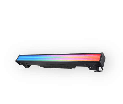
Weatherproof 1 m pixel bar with 168 × 3 W cool-white high-performance LEDs and 768 × 0.5 W RGB multi-chips, electronic frost filter, 16 channel modes and Art-Net
Operating manual. Please read in full before first use and keep for future reference.
Light source
168+768CW + RGB SMD
Length
1 m135 × 145 mm
DMX channels
10–30516 channel modes
IP rating
IP65Outdoor
Lexvision LV-IPBar-SMDForeword · About this document
Foreword
00Welcome
Thank you for choosing the Lexvision LV-IPBar-SMD — a weatherproof pixel bar combining two LED systems: 168 × 3 W cool-white high-performance LEDs for flash and strobe effects plus 768 × 0.5 W RGB multi-chips for color and pixel effects, complemented by an electronically switchable frost filter.
This device is designed for professional use in the field of event technology, e.g. on stage. It is not suitable for household lighting. Only use the device according to the instructions given herein — damages due to failure to follow these operating instructions will void the warranty.
WarrantyNo liability is assumed for material and personal damage caused by improper use or non-compliance with the safety instructions. In such cases the warranty and guarantee will be null and void. Unauthorised rebuilds or modifications of the device are not permitted for reasons of safety and render the warranty invalid.
0.1Scope of Delivery
1 × Lexvision LV-IPBar-SMD
1 × Power cable (IP65 Seetronic)
1 × Operating manual
Optional: rigging hardware, matching P-Con link cables
Lexvision LV-IPBar-SMDContents · Overview
Table of Contents
—Overview
01Safety Instructions04
02Technical Specifications05
03Installation06
04Power, DMX & Art-Net Connection07
05Control Panel & Menu08
5.1Operating Modes in Detail09
06DMX Channel Charts (16 channel modes)11
6.110, 11 and 12-Channel Mode11
6.223-Channel Mode12
6.327-Channel Mode13
6.432-Channel Mode14
6.536-Channel Mode15
6.6Pixel Modes 61 / 64 / 65 CH16
6.7Pixel Modes 85 / 88 / 89 CH17
6.8Pixel Modes 301 / 304 / 305 CH18
07Cleaning & Maintenance19
—CE Compliance Notice20
Lexvision LV-IPBar-SMD01 · Safety Instructions
Chapter 01
01Safety Instructions
Danger of Electric ShockTo reduce the risk of electric shock, do not open any part of the device — there are no serviceable parts inside. Only connect the device to a properly installed mains outlet; the outlet must be protected by a residual current breaker (RCD). Voltage and frequency must exactly match the values stated on the device. If the mains cable is equipped with an earthing contact, it must be connected to an outlet with a protective ground — never defeat the protective ground of a mains cable.
The mains outlet must be easily accessible so that you can unplug the device quickly if need be.
Never touch the mains plug with wet or damp hands. There is the risk of potentially fatal electric shock.
The mains cable must not be bent or squeezed. Keep it away from hot surfaces and sharp edges. Always seize the plug to disconnect — never pull the mains cable.
Unplug the device during lightning storms, when unused for long periods of time, and before cleaning.
The device is suitable for indoor use only. Do not use it outdoors. Never expose it to rain or moisture, and do not store it in rooms exposed to moisture.
Do not expose the device to any high temperatures, direct sunlight, dripping or splashing water, strong vibrations or heavy mechanical stress.
Do not place any objects filled with liquids and no open sources of fire, such as burning candles, on or directly next to the device. Make sure that objects cannot fall into the device, in particular metal parts.
Only have repairs to the device or its mains cable carried out by qualified service personnel. Repairs are required when the device or mains cable is visibly damaged, liquid has been spilled or objects have fallen into the device, the device has been exposed to rain or moisture, has been dropped, or malfunctions occur.
This product is not a toy. Keep it out of the reach of children and pets, do not leave packaging material lying around carelessly, and never leave this device running unattended.
This device may be used only by persons with sufficient physical, sensorial and intellectual abilities and having corresponding knowledge and experience.
up to 8 devices at 230/240 V · up to 4 devices at 110/115 V
Housing & Installation
Cooling
Active, temperature-controlled fan, with over-temperature protection
Installation
2 × hanging point · 1 × safety attachment point (two eyelets for the safety bond)
Dimensions
Length 1000 mm · depth 135 mm · height 145 mm
Weight
11 kg net
Self Test
Function test
All functions testable (testing)
Effect test
Dimmer · red · green · blue · white · frost
Lexvision LV-IPBar-SMD03 · Installation
Chapter 03
03Installation
The device may be fastened to a truss or similar rigging structure. It must never be fixed swinging freely in the room.
The mounting point must safely bear the weight of the fixture; the fixture must additionally be secured with a suitable safety cable of sufficient load rating in accordance with local regulations and laws.
Block access below the work area and work from a stable platform when installing the device.
Use rigging hardware that is compatible with the structure and capable of bearing the weight of the device.
Secure the device with a safety bond or other secondary attachment. This secondary safety attachment must be sufficiently dimensioned in accordance with the latest industrial safety regulations and constructed in a way that no part of the installation can fall down if the main attachment fails. There are two appropriate eyelets mounted on the device for fixation of the safety bond. Fasten the safety bond in such a way that, in the event of a fall, the maximum drop distance of the device will not exceed 20 cm.
To align the device, release the fixation screws at the mounting bracket, adjust the desired inclination angle and retighten the fixation screws.
After installation, the device requires periodic inspections to prevent the possibility of rust, deformation and looseness.
Mounting to the support structureLexvision LV-IPBar-SMD04 · Power, DMX & Art-Net Connection
Chapter 04
04Power, DMX & Art-Net Connection
4.1Power Connection
The device uses an auto-range power supply that accepts input voltages between 100 and 240 volts.
Connect the device via the mains cable to a grounded mains socket. The unit is thus switched on.
To switch off the unit, disconnect the power plug.
Do not connect the unit to the mains voltage via a dimmer. For a more convenient operation, use a mains outlet which is switchable.
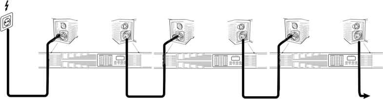
The POWER OUT jack allows for power supply of further devices: connect POWER OUT to the POWER IN of the next unit until all units are connected. Matching power cables with P-Con plugs are available as accessories. In this manner, up to 8 devices can be linked at 230/240 V input voltage and up to 4 devices at 110/115 V input voltage.
4.2DMX512 Connection
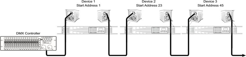
A DMX512 data link is required in order to control the device via DMX. The device provides 3-pin XLR connectors for the DMX connection.
Connect the output of your DMX controller to the DMX input (DMX IN) of the device with a DMX cable.
Connect the DMX output (DMX OUT) of the device to the DMX input of the next unit in the chain. Always connect one output to the input of the next unit until all units are connected.
At the last unit, the DMX cable has to be terminated. Plug the terminator with a 120 Ω resistor between Signal (−) and Signal (+) in the DMX output of the last unit.
If the cable length exceeds 300 m or the number of DMX devices is greater than 32, it is recommended to insert a DMX level amplifier to ensure proper data transmission.
4.3Art-Net
RJ45 connectors (IN/OUT) are provided for network control. Art-Net is activated and configured via the device menu.
Avoid Overlapping AddressesMake sure that you do not have any overlapping channels in order to control each device correctly and independently from any other fixture on the DMX chain. If several devices are addressed to the same address, they will work synchronously.
Linking multiple fixturesLexvision LV-IPBar-SMD05 · Control Panel & Menu
Chapter 05
05Control Panel & Menu
Operation via four buttons: MENU (enter the menu or return to the main menu), UP and DOWN (navigate and change values), ENTER (confirm the selection). If no control signals are available the display will blink; the display will not blink when DMX signals are being received.
Show programs AUTO 01 – AUTO 10, running speed "Speed" 000 (slow) to 255 (fast)
Effect of Auto
Brightness "Dimmer" 000–255 and strobe speed "Strobe" 000–255 for the automatic programs
Mas Mode
Define master or slave operation (yes / no)
MANUAL
Manually set dimmer, strobe, frost as well as red, green, blue and white (000–255 each)
Back Light
On (always on) · 60 s · 120 s · 300 s
Temp
Temp 1 — temperature at the LEDs · Temp 2 — inner temperature of the device
Dimmer Curve
Curve 1 linear · curve 2 square law · curve 3 inverse square law · curve 4 S-curve
Fade Time
Fade time 00 (fast) to 07 (slow)
Display Reverse
Reverse the display by 180° (yes / no)
Brightness
1 – 100
Language
English
Lock
On / Off
Service
Passcode · fine · dimmer · red · green · blue · white
Factory Reset
Yes / No
Clear Running Time
Yes / No
Clear LED Hours
Yes / No
Information
Running time · LED hours · SW version · RDM UID · temperature
Lexvision LV-IPBar-SMD05.1 · Operating Modes in Detail (1/2)
5.1Automatic Mode (Auto)
In automatic mode, various show programs are available that run at an adjustable speed. Additionally, a desired color can be set.
Press the MENU button until Auto is indicated in the display. Confirm with the ENTER button.
Use the UP and DOWN buttons to select the desired show program (AUTO 01 to AUTO 10). Confirm with the ENTER button.
The display now indicates Speed. Confirm with the ENTER button and adjust the running speed with the UP and DOWN buttons from 000 (slow) to 255 (fast). Confirm with the ENTER button.
5.1.1Effect of Auto
In this mode you can set the desired brightness and strobe speed of the programs in automatic mode: after selecting Effect of Auto, first set Dimmer (000 dark to 255 bright), then Strobe (000 slow to 255 fast) — confirming each with the ENTER button.
5.1.2Master/Slave Operation (Mas Mode)
Several devices may be interconnected (max. 32). All slave units can then be synchronized and controlled with the master unit without the need for a DMX controller. The devices must be set to the corresponding operating modes. Configure all slave units before connecting the master unit.
Connect the DMX output of the master unit to the DMX input of the first slave unit. Then connect the DMX output of the first slave unit to the DMX input of the second slave unit, etc., until all units are connected in a chain. Make sure the master unit is the first in the chain. Do not connect a DMX controller to the DMX input of the master unit.
Press MENU until Mas Mode is indicated, confirm with ENTER, and use UP/DOWN to select "Yes" (master) or "No" (slave) for each device.
Then set the master unit to the desired operating mode. The interconnected devices will now operate synchronously.
Lexvision LV-IPBar-SMD05.1 · Operating Modes in Detail (2/2)
5.1.3Manual Operation (MANUAL)
In this mode you can manually set the desired brightness, strobe speed and frost effect, as well as the intensity of the colors red, green, blue and white. After selecting MANUAL, set the following in sequence, confirming each with ENTER:
Parameter
Value range
Dimmer
000 (dark) – 255 (bright)
Strobe
000 (slow) – 255 (fast)
Frost
000–100 clear front panel · 101–255 frost effect
Red / Green / Blue / White
000 (dark) – 255 (bright)
5.1.4Dimmer Curves
Curve
Behaviour
Curve 1 — Linear
The brightness increases linearly with the DMX value.
Curve 2 — Square Law
The brightness increases exponentially with the DMX value.
Curve 3 — Inverse Square Law
The brightness increases reverse exponentially with the DMX value.
Curve 4 — S-Curve
The brightness increases S-shaped with the DMX value.
5.1.5Further Settings
Back Light — Display characteristics when the buttons are inactive: On (display always on), 60 s, 120 s or 300 s until switch-off.
Temp — Temp 1 displays the temperature at the LEDs, Temp 2 the inner temperature of the device.
Fade Time — Fade time from 00 (fast) to 07 (slow).
Information — Running time, LED hours, software version, RDM UID and temperature.
The fixture offers 16 channel modes. All channels operate over the value range 000–255. Chapters 6.1 to 6.5 list the base modes in full; chapters 6.6 to 6.8 describe the pixel modes and their channel layout.
6.110 Channels
CH
Function
Value
1
Master dimmer
000 – 255
2
Red 0-100%
000 – 255
3
Green 0-100%
000 – 255
4
Blue 0-100%
000 – 255
5
White 0-100%
000 – 255
6
Flash
000 – 255
7
Special effect (RGB)
000 – 255
8
Macro
000 – 255
9
Special effect (W)
000 – 255
10
Frost (electronic frost filter)
000 – 255
6.1.111 Channels
CH
Function
Value
1
Dimmer (RGB)
000 – 255
2
Red 0-100%
000 – 255
3
Green 0-100%
000 – 255
4
Blue 0-100%
000 – 255
5
Strobe (RGB)
000 – 255
6
Special effect (RGB)
000 – 255
7
Macro
000 – 255
8
White 0-100%
000 – 255
9
Strobe (White)
000 – 255
10
Special effect (W)
000 – 255
11
Frost (electronic frost filter)
000 – 255
6.1.212 Channels
CH
Function
Value
1
Red 0-100%
000 – 255
2
Strobe (Red)
000 – 255
3
Green 0-100%
000 – 255
4
Strobe (Green)
000 – 255
5
Blue 0-100%
000 – 255
6
Strobe (Blue)
000 – 255
7
White 0-100%
000 – 255
8
Strobe (White)
000 – 255
9
Special effect (W)
000 – 255
10
Special effect (RGB)
000 – 255
11
Macro
000 – 255
12
Frost (electronic frost filter)
000 – 255
Lexvision LV-IPBar-SMD06.2 · 23-Channel Mode
6.223-Channel Mode
CH
Function
Value
1
Master dimmer
000 – 255
2
16 bit dimmer
000 – 255
3
Color temperature (CTO)
000 – 255
4
Red 0-100%
000 – 255
5
Green 0-100%
000 – 255
6
Blue 0-100%
000 – 255
7
White 0-100%
000 – 255
8
Strobe (RGB) intensity, from minimum to maximum
000 – 255
9
Strobe
000 – 255
10
Strobe rate
000 – 255
11
Rainbow effect
000–005 No function
006–255 Rainbow effect
12
Macro
000 – 255
13
Special effect (RGB)
000 – 255
14
Speed of special effect (RGB)
000 – 255
15
Fade (RGB)
000 – 255
16
Different background color macros
000 – 255
17
Background color brightness
000 – 255
18
Direction (RGB)
000 – 255
19
Special effect (W)
000 – 255
20
Speed of special effect (W)
000 – 255
21
Fade (W)
000 – 255
22
Direction (W)
000 – 255
23
Frost (electronic frost filter)
000 – 255
Lexvision LV-IPBar-SMD06.3 · 27-Channel Mode
6.327-Channel Mode
CH
Function
Value
1
Master dimmer
000 – 255
2
16 bit dimmer
000 – 255
3
Color temperature (CTO)
000 – 255
4
Red 0-100%
000 – 255
5
Green 0-100%
000 – 255
6
Blue 0-100%
000 – 255
7
Strobe (RGB) intensity, from minimum to maximum
000 – 255
8
Strobe
000 – 255
9
Strobe rate
000 – 255
10
Rainbow effect
000–005 No function
006–255 Rainbow effect
11
Speed of rainbow effect
000 – 255
12
Special effect (RGB)
000 – 255
13
Speed of special effect (RGB)
000 – 255
14
Fade (RGB)
000 – 255
15
Different background color macros
000 – 255
16
Background color brightness
000 – 255
17
Direction (RGB)
000 – 255
18
White 0-100%
000 – 255
19
16 bit dimmer (White)
000 – 255
20
Strobe intensity (White)
000 – 255
21
Strobe duration (White)
000 – 255
22
Strobe rate
000 – 255
23
Special effect (W)
000 – 255
24
Speed of special effect (W)
000 – 255
25
Fade (W)
000 – 255
26
Direction (W)
000 – 255
27
Frost (electronic frost filter)
000 – 255
Lexvision LV-IPBar-SMD06.4 · 32-Channel Mode
6.432-Channel Mode
From the 32-channel mode onwards the RGB effects are split into two independent groups, A and B. Channel 19 copies the group A settings to group B.
These three modes address the RGB area in 16 segments (red, green, blue each) and the white area in 12 segments individually. All segment channels dim linearly from 000 to 255 (0–100 %).
61-Channel Mode
CH
Function
Value
1
Frost (electronic frost filter)
000 – 255
2
Red 1
000 – 255
3
Green 1
000 – 255
4
Blue 1
000 – 255
…
…
…
47
Red 16
000 – 255
48
Green 16
000 – 255
49
Blue 16
000 – 255
50
White 1
000 – 255
…
…
…
61
White 12
000 – 255
64-Channel Mode
CH
Function
Value
1
Master dimmer
000 – 255
2
16 bit dimmer
000 – 255
3
Frost (electronic frost filter)
000 – 255
4
Strobe (RGB)
000 – 255
5
Red 1
000 – 255
6
Green 1
000 – 255
7
Blue 1
000 – 255
…
…
…
50
Red 16
000 – 255
51
Green 16
000 – 255
52
Blue 16
000 – 255
53
White 1
000 – 255
…
…
…
64
White 12
000 – 255
65-Channel Mode — identical to the 64-channel mode, plus channel 65: strobe (white), 000–255.
The highest-resolution modes address the RGB area in 96 segments and the white area in 12 segments individually. The 305-channel mode is the full configuration and the factory default of the fixture.
301-Channel Mode
CH
Function
Value
1
Frost (electronic frost filter)
000 – 255
2
Red 1
000 – 255
3
Green 1
000 – 255
4
Blue 1
000 – 255
…
…
…
287
Red 96
000 – 255
288
Green 96
000 – 255
289
Blue 96
000 – 255
290
White 1
000 – 255
…
…
…
301
White 12
000 – 255
304-Channel Mode
CH
Function
Value
1
Master dimmer
000 – 255
2
16 bit dimmer
000 – 255
3
Frost (electronic frost filter)
000 – 255
4
Strobe (RGB)
000 – 255
5
Red 1
000 – 255
6
Green 1
000 – 255
7
Blue 1
000 – 255
…
…
…
290
Red 96
000 – 255
291
Green 96
000 – 255
292
Blue 96
000 – 255
293
White 1
000 – 255
…
…
…
304
White 12
000 – 255
305-Channel Mode — identical to the 304-channel mode, plus channel 305: strobe (white), 000–255.
Segment NumberingSegments are numbered consecutively along the length of the bar. In the modes with effect channels (32 CH and above) the direction of the effects can be reversed via the "direction (RGB)" and "direction (W)" channels.
Lexvision LV-IPBar-SMD07 · Cleaning & Maintenance
Chapter 07
07Cleaning & Maintenance
The outside of the device should be cleaned periodically to remove contaminants such as dust. The lenses in particular should be clean to ensure that light will be emitted at maximum brightness.
Disconnect the device from power and allow it to cool before cleaning.
Clean the surface with a soft, lint-free and moistened cloth. Never use alcohol or solvents as these may damage the surface. Make sure that no liquids can enter the device.
The device must be dry before reapplying power.
No Serviceable Parts InsideDo not open the housing and do not try to repair the device yourself as this may result in damage. Maintenance and service operations are only to be carried out by authorized dealers. Should you need spare parts, please use genuine parts.
7.1Protecting the Environment & Disposal
When the device is to be permanently taken out of operation, take it to a local recycling plant for a disposal which is not harmful to the environment. Devices marked with this symbol must not be disposed of as household waste. Contact your retailer or local authorities for more information. Remove any inserted batteries and dispose of them separately from the product.
As the end user you are required by law (Battery Ordinance) to return all used batteries and rechargeable batteries; disposing of them in the household waste is prohibited. You may return your used batteries free of charge to collection points in your municipality and anywhere where batteries and rechargeable batteries are sold. By disposing of used devices and batteries correctly you contribute to the protection of the environment.
Lexvision LV-IPBar-SMD— · CE Compliance Notice
Appendix
—CE Compliance Notice
The manufacturer declares under its sole responsibility that the LV-IPBar-SMD complies with the relevant EU harmonization legislation.
EU Declaration of Conformity
A signed EU Declaration of Conformity exists for this product. It is not part of this manual and can be requested from us at any time — by email to verkauf@lexvision.de or by phone on +49 (0) 651 14567727, stating the product designation.
The signed EU Declaration of Conformity for this product is available upon request from Lexvision GmbH, Waldweg 26, 54636 Sefferweich, Germany.